 Language
Installation of Flexlock Invisible
To ensure Flexlock Invisible and its RFID technology operate to best advantage with user and function cards, the lock may only be fitted to storage units made of wood, plastic or other non-conductive material with a maximum board thickness of 25 mm.
Locks
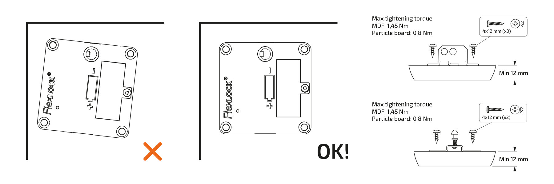
When fitting the lock, first screw in two screws diagonally from each other. Check closure of the storage unit and make any adjustments before tightening the two remaining screws. The door should be at least 14 mm thick. A PZ2 screwdriver is needed for the screws (4 screws: 4.5x35mm).
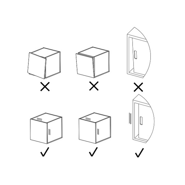
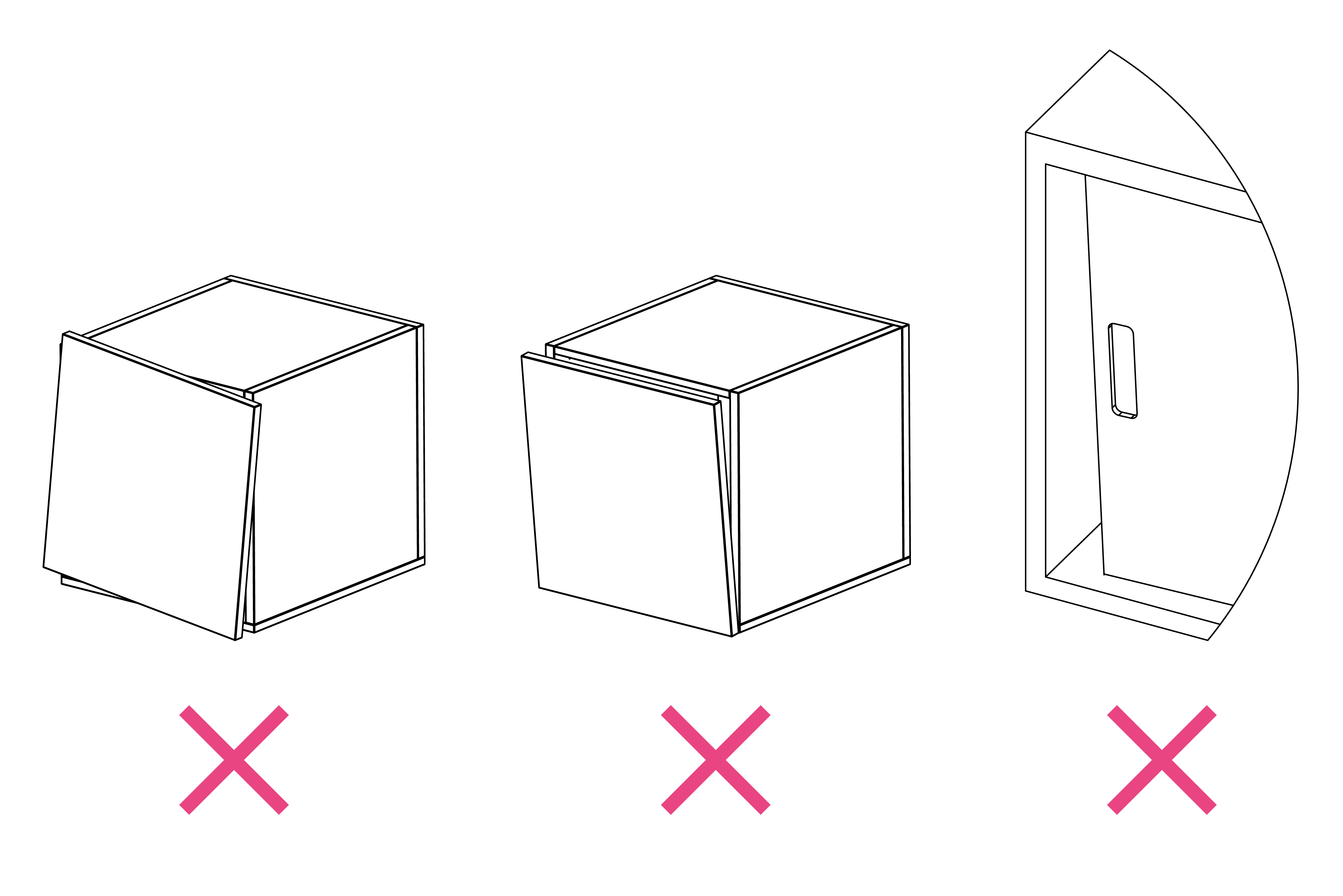
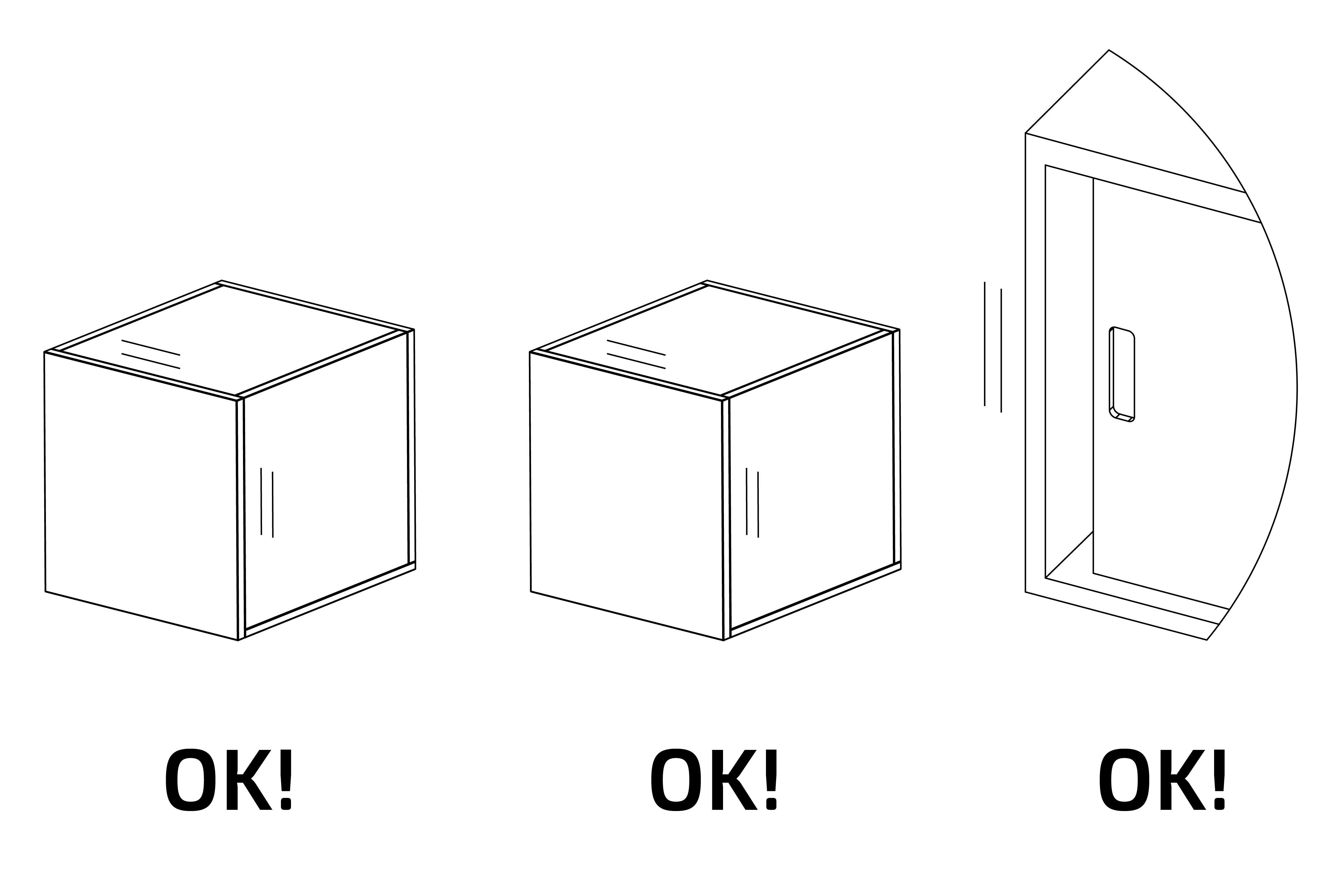
To ensure the lock and lock plate align properly, storage units, doors, drawers, sliding doors, etc. must be assembled parallel and be correctly adjusted. Check this before installation.

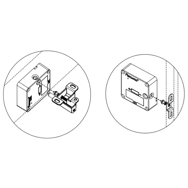
Lock plates
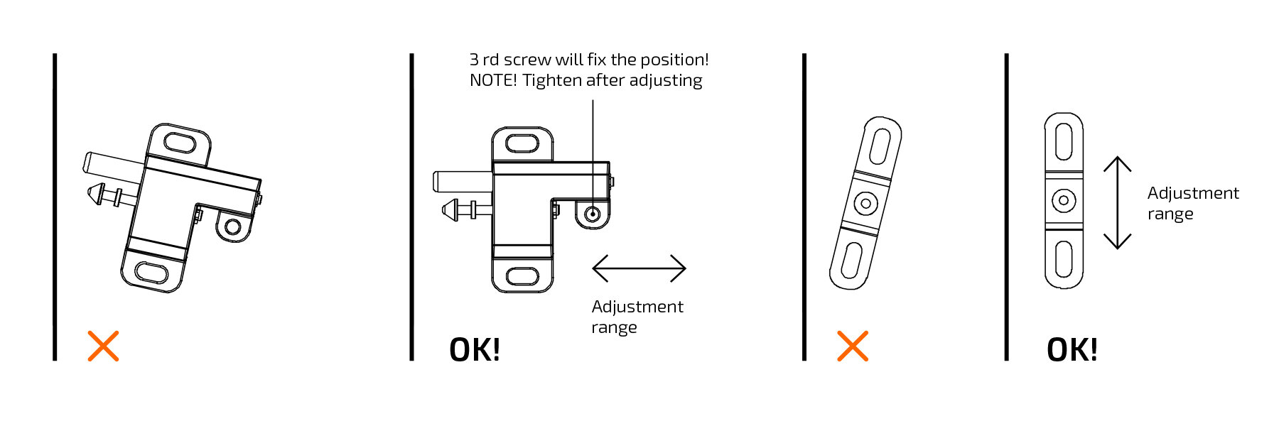
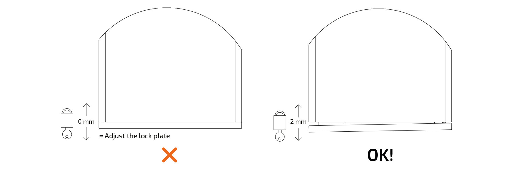
Fit the lock plate so that it is straight. The board of the storage unit must be at least 12 mm thick. A PZ2 screwdriver is needed for the screws (2 or 3 screws (4x12mm) depending on the type of lock plate). Use the adjustment allowance to ensure that there is a gap of 2 mm between the door and storage unit when the lock is locked.
Installation on a sliding door
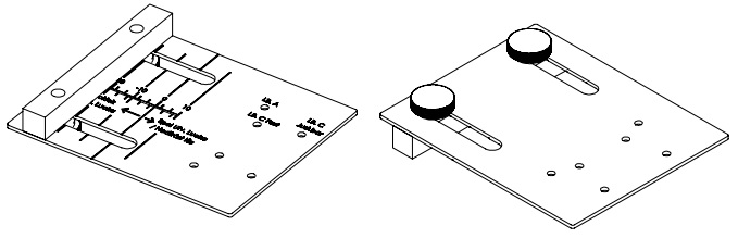
To facilitate positioning of Flexlock with lock plate on sliding doors, Positioning template 171132 and Marking template 171112 are available as accessories.
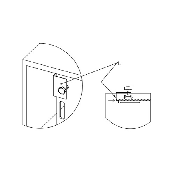
1. Place the positioning template in a suitable position on the sliding door and tighten the template clamp. Make sure you push the template against the edge of the door.
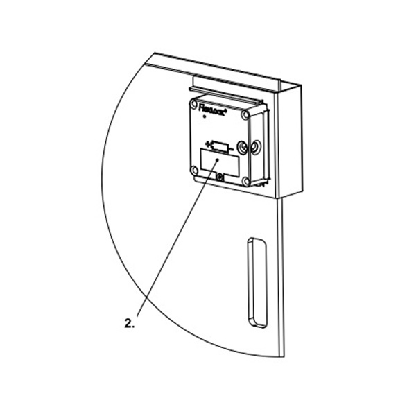
2. Apply double-sided tape to the rear of Flexlock, insert Flexlock into the template and secure it with screws.
Note: Check that the programming card has been added before Flexlock is finally attached. Remove the positioning template.
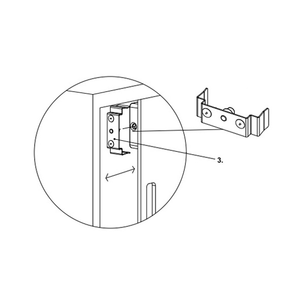
3. Attach the marking template to Flexlock. Then slide the door shut. The template will leave a mark where the lock plate is to be attached (alternatively, you can paint the spikes with a marker pen beforehand). Remove the marking template.
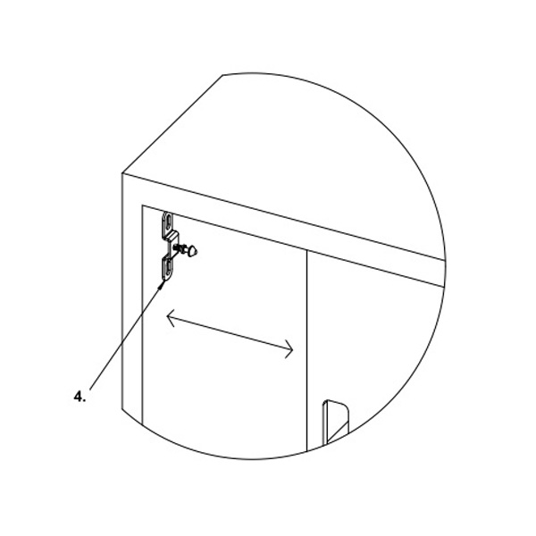
4. Screw the lock plate into position where the marks are. Close the door again to check that everything works properly and that there is a gap of approximately 1.5–2 mm in the locked position. Test locking and opening. (If necessary, adjust the lock plate.)
Installation on a door/drawer
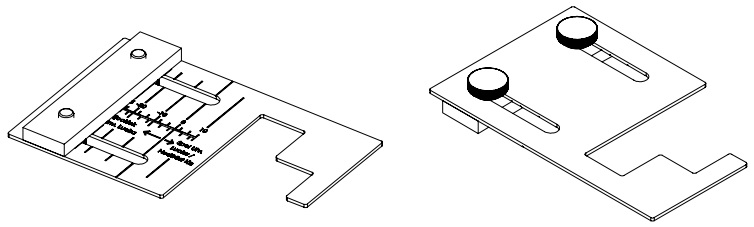
To position Flexlock with lock plate on doors and drawers, Marking template 171241, Dummy lock 171221 and Positioning templates 171151 and 171271 are available as accessories.
Marking template 171241 marks the hole pattern for the lock plate.
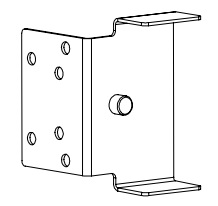
Dummy lock 171221 is used to position Flexlock parallel in relation to the lock plate.
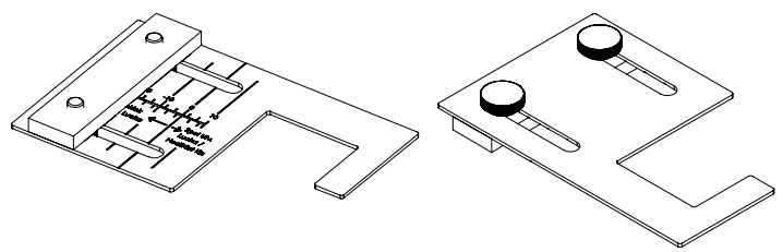
Positioning templates 171151 and 171271 hold the lock plate in the correct position while you insert the screws. Use Positioning template 171151 for Lock plate Catapult.
Use Positioning template 171271 for Lock plate Catapult+.
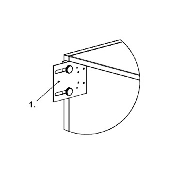
1. Adjust the marking template depending on whether the door/drawer is of inset or overlay type. (See the section Templates.) Position the template at the desired position of the lock plate. Mark or drill the holes.

2. Screw the dummy lock into the hole pattern.
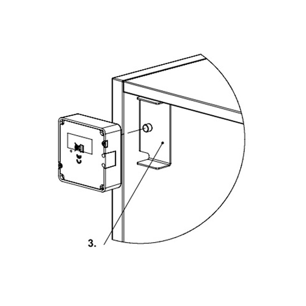
3. Fit Flexlock onto the dummy lock. Apply double-sided tape to the rear of Flexlock. Note: Check that the programming card has been added before Flexlock is finally attached.
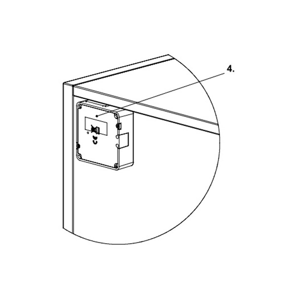
4. Close the door/drawer and open it again. The lock has now attached itself to the door/drawer and can be screwed in position. Remove the dummy lock.
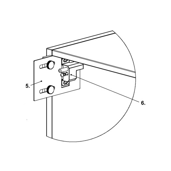
5. Adjust the positioning template in the same way as the marking template. (See Templates.)
6. Position the template next to the hole pattern and secure the lock plate with screws. Close the door/drawer again to check that everything works properly and that there is a gap of approximately 1.5–2 mm in the locked position. Test locking and opening. (If necessary, adjust the lock plate.)
 Svenska
 English (UK/International)
 Deutsch